
A cantilever from a rectangular cross-section is lying on an elastic Winkler foundation and loaded by distributed loading. The image shows the calculation of the maximum deflection and maximum bending moment.
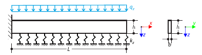
A cantilever from a rectangular cross-section is lying on an elastic Pasternak foundation and loaded by distributed loading. The image shows the calculation of the maximum deflection and maximum bending moment.
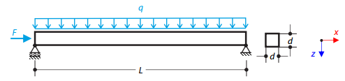
A steel beam with a square cross-section is loaded with an axial force and distributed loading. The image shows the calculation of the maximum bending deflection and critical load factor according to the second-order analysis.
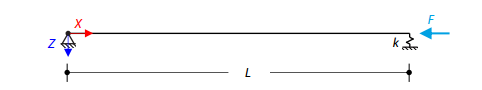
An axially loaded steel beam with a square cross-section is pinned at one end and spring-supported at the other. Two cases with different spring stiffnesses are considered. The verification example solves the calculation of the load factors of the beam in the image using the linear stability analysis.
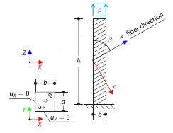
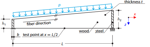
A cantilever with fibers that do not run in direction of the beam axis from a square cross‑section with tensile pressure. Calculate the maximum deflection.
A timber beam reinforced by two steel plates at the ends is loaded by pressure. The wood fibers are parallel to the upper loaded side of the beam. The plastic surface is described according to the Tsai-Wu plasticity theory.
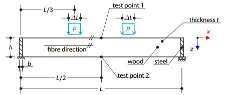
A timber beam reinforced by two steel plates at the ends is loaded by pressure. The wood fibers are parallel to the upper loaded side of the beam. The plastic surface is described according to the Tsai-Wu plasticity theory.
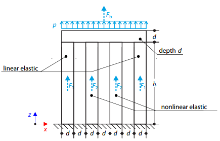
Four columns are fixed at the bottom and connected by a rigid block at the top. The block is loaded by pressure and modeled by an elastic material with a high modulus of elasticity. The outer columns are modeled by linear elastic material and the inner columns by a stress-strain diagram with decaying dependence. Assuming only the small deformation theory and neglecting the structure's self-weight, determine its maximum deflection.
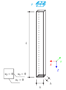
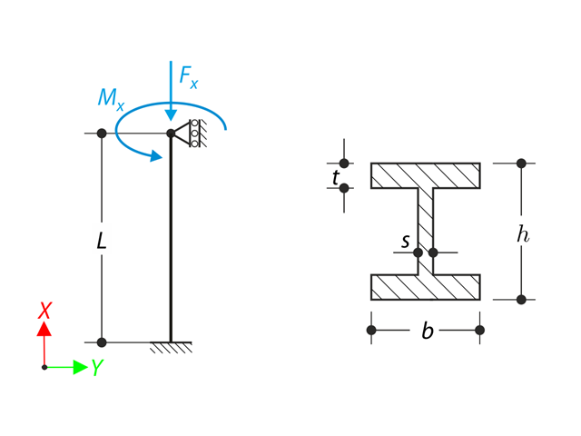
A vertical cantilever with a square cross-section is loaded at the top by tensile pressure. The cantilever consists of an isotropic material. Calculate the deflection.
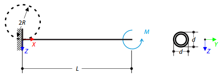
Determine the bending moment which, acting at the free end of the cantilever, will bend the member into a circular shape. Neglecting the beam's self-weight, assuming the large deformation analysis, and loading the cantilever with the moment, determine its maximum deflections.
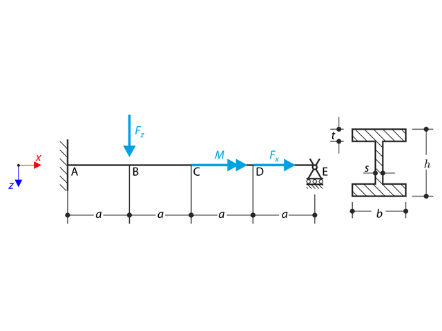
A beam is fully fixed (warping is restricted) on the left end and supported by a fork support (warping is enabled) on the right end. The beam is subjected to a torque, longitudinal force, and transverse force. Determine the behavior of the primary torsional moment, secondary torsional moment, and warping moment. The verification example is based on the example introduced by Gensichen and Lumpe.
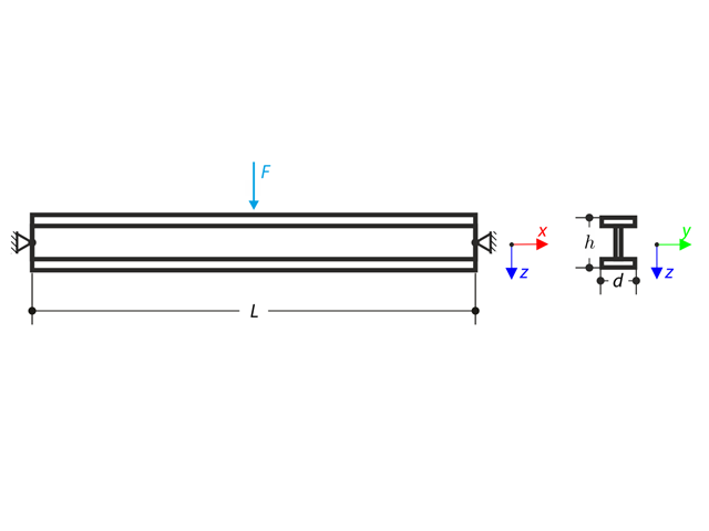
A beam pinned at both ends is loaded with concentrated force in the middle. Neglecting its self-weight and shear stiffness, determine the beam's maximum deflection, normal force, and moment at the mid-span, assuming the second- and third-order analysis.
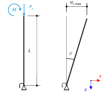
A cantilever is loaded by a moment at its free end. Using the geometrically linear analysis and large deformation analysis, and neglecting the beam's self-weight, determine the maximum deflections at the free end. The verification example is based on the example introduced by Gensichen and Lumpe.
A member with the given boundary conditions is loaded by torsional moment and axial force. Neglecting its self-weight, determine the beam's maximum torsional deformation as well as its inner torsional moment, defined as the sum of a primary torsional moment and torsional moment caused by the normal force. Provide a comparison of those values while assuming or neglecting the influence of the normal force. The verification example is based on the example introduced by Gensichen and Lumpe.
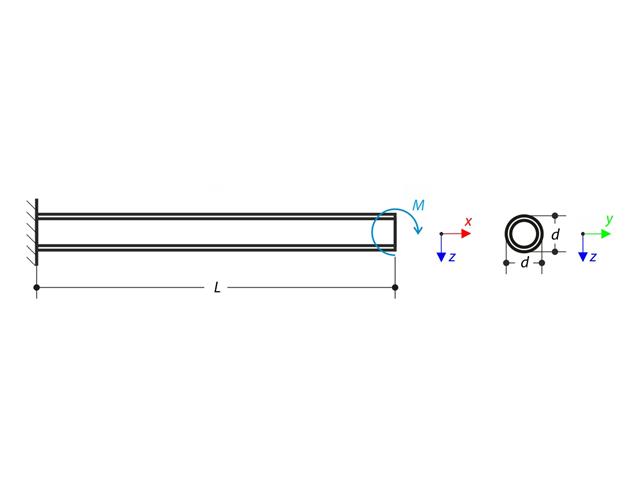
Consider a rigid scaffolding tube, fixed at the bottom using the Scaffolding Nodal Support and loaded by both a moment and a force. Self-weight is not considered. Considering an infinitely rigid beam, determine the maximum radial deflection.
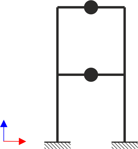
A two‑story, single‑bay frame structure is subjected to earthquake loading. The modulus of elasticity and cross‑section of the frame beams are much larger than those of the columns, so the beams can be considered rigid. The elastic response spectrum is given by the standard SIA 261/1:2003. Neglecting self-weight and assuming the lumped masses are at the floor levels, determine the natural frequencies of the structure. For each frequency obtained, specify the standardized displacements of the floors as well as equivalent forces generated using the elastic response spectrum according to the standard SIA 261/1.2003.
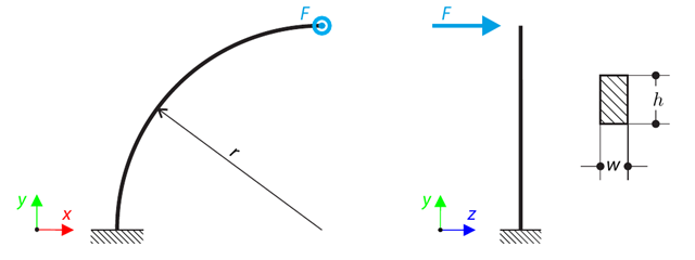
A quarter-circle beam with a rectangular cross-section is loaded by means of an out-of-plane force. This force causes a bending moment, torsional moment, and transverse force. While neglecting self-weight, determine the total deflection of the curved beam.
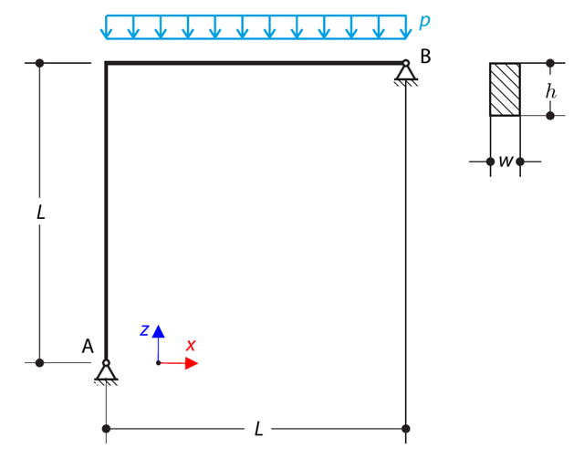
A curved beam consists of two beams with a rectangular cross-section. The horizontal beam is loaded by distributed loading. While neglecting self-weight, determine the maximum stress on the top surface of the horizontal beam.
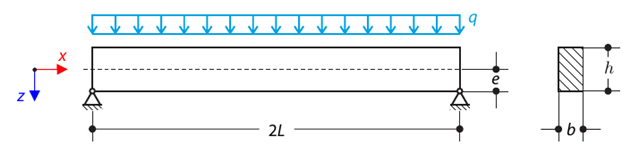
A pinned beam with a rectangular cross‑section is subjected to distributed loading and shifted vertically by eccentricity. Considering the small deformation theory, neglecting the self‑weight, and assuming that the beam is made of isotropic elastic material, determine the maximum deflection.

A column is composed of a concrete section (rectangle 100/200) and a steel section (profile I 200). It is subjected to pressure force. Determine the critical load and corresponding load factor. The theoretical solution is based on the buckling of a simple beam. In this case, two regions have to be taken into account due to different moments of inertia and material properties.